

This post is an introductory tutorial for people interested in producing custom-designed 3D Judaica (such as tzedakah boxes, Shabbat light switch covers, mezuzah cases, and other such items).
First we’ll have an overview of the nature and process of “Do It Yourself” 3D design and printing, and then show how this can be done for creating Judaic objects such as Shabbat light covers and tzedakah boxes. NLEResources.com has previously explored the world of 3D printing previously here.
Designing and making your own Judaica is becoming easier.The availability of easy-to-use software and on-demand printing services has made it possible for “Do it Yourself” (DIY) type individuals—not just professional engineers—to create Judaic designs in 3D and have them printed in plastic, or even metal. Here’s how to get started. I have designed, printed, and assembled tzedakah boxes and Shabbat light switch covers which can be accomplished in the following stages.
STAGE ONE – Procuring a 3D Design Computer Program.
In order to design and print 3D objects such as Judaica, you’ll need a 3d CAD program. There are several 3D software programs which most computers will run just fine. I have been using a $100 tablet pc just fine with an external mouse and keyboard. Some new software now requires a 64bit operating system, some do not, and just make sure you got a 1gb of free space to install the program. If you prefer, you can get a faster machine.
Creo elements, is a free program. Its good enough for making most parts. It is a bit harder for a beginner to figure out and it is not as advanced as the other good option, Autodesk Inventor. But, being free, bh.
Autodesk Inventor LT is the program I recommend for a beginner. It is advanced enough to make almost anything you want, with a hierarchy tree to undo different design changes. It is very intuitive, there are tutorials online, and it costs only $50 a month. Their newest version may require a 64 bit pc if it’s the latest windows operating system, or 32 bit might also work if it’s an older version of Windows.
Another program is Blender if someone is interested in making graphics/animations of 3d models, it is quite more complex of a program.
STAGE TWO – Designing the Object.
When you think of a new idea, it might be a good idea to sketch it out on paper first. Designing 3D on the computer can be used for:
-3d printed objects
-3d animations
-3d images
All 3D CAD programs work by three common steps:
- Make/select plane
- Draw sketch
- Pull sketch
With these three steps, a person can pretty much make any basic object.
STAGE 3 – 3D PRINTING.
If you’re planning to print a fair amount of Judaica, you might consider purchasing a 3D printer for plastic or metal. Alternatively, you can also print your Judaica by sending your designs to on-demand 3D printing services that can even print ceramic, stone, and silver. For 3D printing, a person should be handy, soldering iron, computer savvy, building things, etc.
Here’s some overview information about 3d printing:
-it’s not completely easy making sure machines are running fine, things need to be adjusted sometimes.
-machines needs to be in fire safe place, on metal table, smoke detector, etc. (one connector melted and started to smoke in my machine once)
-small parts print quick, but large parts can require 20-40 hours for a single print, sometimes there can be an error midway
-there are some fumes, they say it’s safe, but who knows
-the surface finish is not completely smooth, because it is printed layer by layer
-3d printed parts left in a hot car might deform
-some inexpensive parts in the print head wear and need to be replaced, maybe new $5 copper print nozzle and some other small parts once every couple months. Good to have spare parts handy.
-For the plastic printing material, there are different several options, the standard now is that they are all also size 1.75mm, not 3.00mm:
PLA: Supposed to be the safest for fumes, prints at lower temperature, doesnt warp and crack.
SoftPLA: rarely needed, but if you need a part that is rubbery like a rubber band, this is it. it is more complicated to setup, prints much slower.
ABS: Only use if you needed, toxic fumes, parts start warping if more than 1 inch in size. only main benefit is it can withstand higher temperatures, if you neeed a part that will be in contact with heat, then ABS has the advantage.
-plastic filament cost roughly $15 / 1kg
-to calibrate the machines, to adjust settings on the 3d printed, most machines use a free program called Arduino. you download the program onto your pc, adjust the settings and upload to the machine through usb. Its not too difficult, just sometimes need to search online to find answers, mostly just changing a digit here or there.
– The cheapest generic brand 3d printer I had ($200), had a controller board that stopped working after 3 months. Might be worth it to pay $50 for more reliability…
There are 2 main types of desktop 3d printers:
Cartesian
A cartesian 3d printer is easier to figure out and build for a beginner. Folger Tech Prusa i3 is an okay one to start out with. The only thing is if you are planning on printing a lot, you may want to find a bowden style cartesian printer:
so the filament needs a motor to push it through the nozzle. The motor can be either:
– direct drive: attached right on top of the print head and so the print head is much heavier having this big motor on top of it. this is easier to setup for a beginner.
– bowden/detached from printhead: mounted away, like 12 inches away, more complex to setup, but maybe more reliable for months of printing. the print head is much lighter with the motor just sitting on the table.
Also, you should get the LCD display controller so you can print off an sd card without a computer attached.
Delta
example is Folger Tech Kossel 2020. some advantages of a delta printer is that is is slightly faster, smoother and more accurate surface finish, once its calibrated it seems to work a bit more reliably, seems to print circular shapes good. Calibrating was more complicated. I dont recommend using the auto calibration. Couldnt calibrate as good as the cartesian setup. For some parts, need better slicing software like s3d that costs $. runs more quietly. Power connector melted for some reason, ended up soldering in power leads directly, then working again. Lcd/sd screen stopped working, solved by plugging in usb for powering the screen. Have issue of wavy part on one of the printers. Maybe other brands delta would work better. Ultimately, the delta printer is useful for some parts. Round parts turn out better, and parts that need higher precision, sometimes the smoother surface looks better, and it can print taller objects.
3d Printing /slicing software: so this is the final step if operating your own 3d printer. for the 3d printer motors to move or the print nozzle to heat up, it needs codes sent to it. the two most common programs are:
Repitier : Free slicing software, inside the program i recommend using the cura slicing engine.
Simplify3D : costs $150, has more print adjustment options, for a delta printer, can actually make surface turn out nicer, for cartesian, both print about the same quality.
expect 3 or so months of printing before you figure out all the settings.
Designing a Shabbat Light Switch Cover & Pushka in Creo Elements 3D Design Software:

once you loaded up Creo elements, click this more button to expand the visible tools

1. here we primarily only use the workplane button. it is used if a new sketch needs to be made on a new surface, just click the button and select the options where to make the plane for the sketch. when you open the program, there is automatically a plane ready to be sketch on.
2. here you can begin to sketch, you can choose from line, rectangle, circle, arc. spline alaws for curved lines but it is a little bit tricky to work with, but its okay.
3.also the project button is useful if you need to project a line from a shape to a sketch. another button that is used is equidistance, that is if you need to offset a line a distance, doesnt work great here, sometimes have to click around, but it works eventually.
4. here i have mostly used the move command to move a sketch and trim (had to click drop down and select 3rd bottom one, dont understand how other two trims work)
5.pull command, this is commonly used button, to pull a sketch to make it have hight, 3d.
6.Modify also is a commonly used button, you can adjust the height of an object, either up or down.
7. Blend and Chamfer are also commonly used for smoothing an edge.
8. lastly, this section on the side shows parts (that begin with P) and workplane sketches (that begin with W) you can have many parts and many different sketches. unchecking the box next to them hides them. you can click and chose to delete also.
Designing a Shabbat Switch Cover in 3D cad:

Dimensions of shabbat switch cover

1.we will begin by sketching the outline of the holder. i have attached the dimensions. you can rotate the workplane with the middle mouse botton. sometimes you have to click the upper left hand green checkmark when done with drawing part.
to enter an exact measurement, click tab on keyboard enter in length in mm, and then enter.

2. Now we will use the pull button to give it some width, making it into a three dimensional part. for the switch cover you can make it as wide as your switch is, to cover a single flip switch i do 26mm. again you can rotate with middle button to see how the 3d part looks. click on the green checkmark to finish this command. remember to save your work, click file save, (then click all objects, and keep in this .pk2 creo format)

3.next we will make a the top of the shabbat switch cover. similar process, just now we will need to create a second part. this requires a couple of clicks.
we will need to make a second sketch, so uncheck the box next to the current sketch (w1) on the left hand column
next we will need to make a new sketch on a new workplane, so click workplane, par to face, and click on the top or bottom face of the holder, then the green checkmark. notice you have option when creating new workplane to offset it, can be handy in future to know.

4. going according the the attached reference dimensions, make the top cover side view sketch. if lines are intersecting, you can use the trim command. click the green checkmark when completed.

5.now we are ready to pull again and make this top part. this one we can pull 27mm.
this is important, after clicking the pull button, enter in a new part number (like p2). this will keep the two parts seperate,so when going to fabricate these parts, they can be seperate files. after typing p2, distance 27, click the green checkmark. there might be more than one part that is created for the top parts, thats okay, as long as its not one part.

6. the top part is almost ready. we need to add the sides. we will do this similarly by making two new sketches, one on each side and pulling them.
so, uncheck the w2 plane sketch to hide it. click workplane again, par to face, click on the side of the top part, then the green check mark to complete. now we will make a side sketch.
here we will use a new command, the project button. we do this because we want the sketch to line up with the part that is there. click on project, then face(this is the most common projection used), then click on the two parts of the top sketch, then green checkmark to complete command.
now we can sketch more lines to make what we want for the sides. and trim unneccessary lines. when the sketch is ready, we go again to the pull button.
this is important, click part, in the options box, then click on your top part (this way this new modification is added to the top switch cover part), then give it a distance, in our case 3mm. (generally 2-3mm is thick enough for these kind of parts), then click green check mark to complete.
do the same for the other side.

7. there might be a little part that didnt get joined on the back of the top cover. find it in the column on the left and delete it, and make it new, attached to the top part. for some reason when we make the top cover, it made it into two parts, because the two sketches werent joined. so once the little piece is deleted, make a new workplane on the correct location, draw the sketch, pull it, selecting the top cover for part to be added to.

8. last step if you want, you can smooth the corners, click blend, click an edge, then set the radius size, click on the next edge, radius size, do all the edges that need to be done, then click the green checkmark to finalize.

9. now that the parts are done, it is time to export them in .stl file format for 3d printing. click file, save, then click select (upper left), click on one of the two parts, now select in drop down, file type as STL, click options on right, and for distance, add two zero’s after the dot, (we want to make it a finer detail, for some reason the distance is set too low and so it needs to be made finer), close the option box, now give it a file name. now do the same thing for the second part. now you have both parts saved in stl for 3d printing.
if you need to ever select more than one part for a single stl file, you can hold shift and select more parts and click middle button on mouse when done selecting to complete.
disregard any messege that might say part is in negative space, part is made fine.
Designing a Pushka in Creo Elements 3D cad:

To begin, to sketch the first sketch, it would be helpful to make the workplane straight on, click the view tab, and then click the view by button.

There are many ways to make the same shape in 3d cad. begin by making this side of of the pushka. then, to make the wall thickness, click equidistance, click on the line in two spots, then type in 2.5mm (this will be our wall thickness of the box) and then the green checkmark to complete.

make sure you have also sketched a little slot for the back cover to slide into as in the picture, just a 2.5mm gap plus .4mm for space on each side for it to move, so 3.3mm gap. then we will extrude this, in this example 110mm.

now we need to make the sides of the box. click on the workplane button, par to face, and click on the side.

now, we want to make a rectangle that matches up exactly to the corners, it should snap automatically, if it doesnt, you can click project, face, and click on the side and it will project all the lines.

once you have a rectangle, pull it 2.5mm. do the same for the other side. To make a box we could have gone another route from the beginning, and used the shell command, by making a cube and then clicking shell and setting the thickness to 2.5mm. sometimes the shell command is the way to go, especially if its a complex shape.

we will now make a opening on the back. Make a new plane on the back, clicking par to face and then on the surface.

next, to get some reference lines to work from, you can click project face and click on the face.

next work on making a sketch for the opening, and arced top or a pointed top are best for 3d printing, a flat top wouldnt print smoothly, because it prints layer by layer, and a big overhang would droop. you can use the arc button to make an arc.

then trim off and delete all extra lines around the arc, and then pull it -10 or so distance for it to remove the material.

next we can make the slot on top. again, make a workplane there, par to face.

sketck out the slot, and pull it -5mm to remove the material.

next, we can make the slider board. make a new workplane par to face on the top.

project the sketch of the current slot, then offset it equidistance 0.4mm.

next we do the pull command. this is important,make sure to type in a new name for part, so it creates a second separate part. Then to know exactly how far the cover should go, click type, to faces, and then click inside the box on the bottom, so it will go to that distance.

this is how it looks this far, its getting there.

now , we have to adjust the top of the box for better 3d printing. because it is flat on top, with the way it is currently modeled, it would drop during printing that first layer such a big span. so how we can fix it? by making the top layer thicker, and adding an angle / chamfer so its more gradual. so click the modify button, then click the bottom of the top from inside the box, add a distance of 2mm(to make it 2mm thicker) and then the green checkmark.

next, click the chamfer button, for type, choose dist/dist, then set a distance such as 20mm and 3 mm. so now looking from the inside, we see that each layer would be a gradual change and will print nicely.

next we can make a little notch on top for pulling up the slider board. just make a plane, make a sketch for a rectangle, and pull it to face, just make sure your modifying the right part by clicking part and then the box. choose remove material .

now that we have a little cutout, click workplane, part to face on the back cover.

make a rectangle, and pull it to face of the outside of the box. make sure for part, that the slider board is selected.

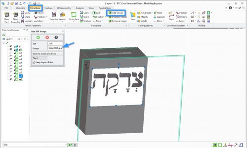
Next we make the tzedakah text on the front of the box. click workplane and par to face.

Next we import an image onto the face. click the structure tab, then add image, and click image, and on your computer select your image (for this example i scanned the tzedakah text from a book). You can adjust the size, rotate it, and position it with the bounding box.

Next we will trace the letters. Choose the spline with control. in the options box chose it to be a closed spline shape, and click around the outside edge. click the green checkmark when done with one letter. do this individually for each letter. This requires some practice and and knowhow. we will then need to clean up the sketh/spline next.

You can also just use regular straight lines for areas that are straight. to adjust the curve, which you probably will need to do, click more, move control point, and click on a black dot that is a control point to move. next you can trim all extra lines.

now, we pull the text. select the box for the part, for distance put 1.5mm.

to make hanging holes for the box, make sketch on the back such as these and pull them through (removing the material) up until the middle of the groove. you only need one, two or three hanging holes, 5 holes in this design was just done for an interesting design.

then to make space for the head of the hanging screw, remove some of the material by the hanging holes in slider board. To know where to remove the material, you can project the sketch of the box onto the slider board.

there you go, now you can save the box as an stl, click select, click on the box, in options, make the distance more fine by adding two zero’s after the decimal point. and do the same for the cover.